Laser Displacement Sensor: Study Work Piece Measurement on a 5-Axis Controlled machining Center On-Machine
 |
| Laser Displacement Sensor |
Concept of Machine Measurement On 5-Axis Control
During measurement activities, the laser vector is traced using a Laser Displacement Sensor on a 3-axis controlled machine tool. On-machine workpiece measuring is traditionally done by tracing the surface of the workpiece while simultaneously controlling two axes on a three-axis controlled machining centre.
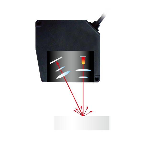
Despite the sensor's strong form measurement capability, a measurement error occurs when the laser vector is angled against the measurement surface. Furthermore, measuring a surface is impossible if the laser vector is almost parallel to the measurement surface. Die and moulds typically have a steep inclination, which leads to measuring errors. Depicts the principle of the Laser Displacement Sensor used in this study. This is a major issue when measuring precision shapes with a three-dimensional free form, such as dies and moulds. As a result, in order to do surface measurement with high accuracy, it is important to aim the laser to the normal direction of the surface as accurately as possible. Then, as previously stated, we attempt to measure the surface using the additional two rotating axes of a 5-axis machining centre.
How a laser vector is traced using spindle orientation control on a five-axis machining centre. Not only does this method reduce measurement error, but it also allows for any surface measurements, including convex dies. As a result, on-machine workpiece measuring on a 5-axis controlled machining centre has an advantage for after-machining workpiece measurement.
Distortion and Temperature
Micro-Epsilon LDS, model LLT 28x0-100, and Micro-Epsilon controller scan CONTROL 28x0 are used to evaluate distortion. As shown in Figure 9.3B, the LDS is positioned to measure the longitudinal bowing distortion mode in the z-direction at the free end of the substrate. The LDS aims at a spot around 6.3 mm away from the substrate's free end. The LDS analogue voltage signal is read using a National Instruments 9250 module. The four thermocouples (0.25 mm diameter) that were used to monitor in-situ temperature Thermocouples 1–3 are situated 63.5 mm from the clamped end of the substrate, near the centre of the substrate, and 6.35 mm from the free end of the substrate, respectively, and measure the temperature on the bottom of the substrate, parallel to the axis of deposition.
The Laser Displacement Sensor uses the triangulation method. The measurement resolution of dimension is good when compared to other measuring devices, and measurement can be applied even if the measuring surface is glossy metal. Thermocouple 4 measures temperature along the deposition axis, on the top edge, at the substrate's free end. The thermocouples are positioned so that temperature readings may be taken at various positions on the substrate without interfering with the LDS. The thermocouple analogue voltage signals are read using a National Instruments 9213 module.


Comments
Post a Comment